High Voltage and X-Ray Experiments
Text and Graphics Copyright © 2005− 2008 Henning Umland
The following descriptions are given for the purpose of information only. I do not encourage ANYBODY to conduct experiments like those shown below, and I do not assume liability for any damage resulting from such experiments. People working with high voltage and X-rays should have a solid background in physics and electronics and should know what they are doing. The high voltage sources described here are much more powerful than generators of static electricity like, e. g., influence machines, Van de Graaff generators, etc. High voltage can kill instantly, X-rays in the long run (radiation sickness, cancer) if not handled properly.
Making Photographic X-Ray Images (I)
Photographic materials (film or paper) used for ordinary photography are also sensitive to X-rays. However, X-ray photography differs from visible-light photography in that the usual lens-based optics can not be used because refractive indices are very low in this range of wave lenghts (λ < 10nm). X-ray photos of objects, called radiographs, are made in transmission mode, i. e., the object is in the optical path of X-rays originating from the focal spot of an X-ray tube. On their way to the film, the X-rays pass through the object and are absorbed to a certain extent, depending on composition, density and thickness of the object. Thus, the image obtained after developing the photographic material shows a shadow of the object obtained by central projection. This image is a negative, i. e., the shadows have lighter shades of grey on a dark background. Shadow images of inhomogeneous objects can reveal details of their internal structure. Since the focal spot of the tube is not a dimensionless point, the object should be placed as close to the film or paper as possible to get sharp images.
The optimum time of exposure depends on many factors and has to be found by experiment. There are a few rules regarding image brightness and contrast:
The following radiographs were made with the small Coolidge tube described earlier (60mAs @ 50kV, distance
= 40cm). The photographic material was ordinary resin-coated black & white paper (grade 4, "hard") made by
TETENAL, Germany. I used this because I still have a huge stock in my refrigerator (I was a dedicated b/w
photographer in the eighties and nineties). Paper has the advantage over film that only a cheap flatbed scanner
without transparency adapter is required for processing the image after it has been developed. The drawbacks
of paper are low contrast and long exposure time due to low sensitivity. Material (film or paper) designed
for X-ray photography has a much higher contrast due to thicker emulsion layers and higher silver content.
I used graphic editors (PhotoFiltre 5.6, later: GIMP) to invert the images and to increase the contrast.
Although the format of the paper was only 9×13 cm, I found that it can be put into a 4×5" sheet
film holder to protect it from visible light. The plastic cover is virtually no obstacle for X-rays.
Here is the developer formulation I used (Kodak D-72):
| Metol | 3g |
| Hydroquinone | 12g |
| Sodium Sulfite | 45g |
| Sodium Carbonate, anhydrous | 68g |
| Potassium Bromide | 2g |
| Water, deionized | ad 1000ml |
The paper was developed for 3 minutes at room temperature (20°C), then rinsed with water for 1 minute (no stop bath), treated with the fixer (10% solution of ammonium thiosulfate) for 2 minutes, and finally rinsed with water again for 2 minutes.
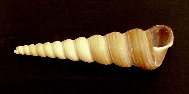
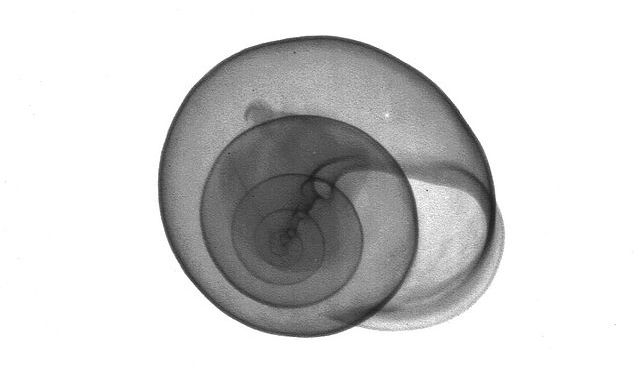
For my first radiograph, I chose a small snail shell (7.5cm long) as a test object. After a few trials, I found the best operating parameters. The results are shown below. The contrast of the print was rather low. Therefore, I used a graphic editor to improve image quality. I also created an inverted image which I find more appealing. The radiograph reveals some deposits deep inside the shell which are not visible in the color photo.
|
Color Photo of Snail Shell
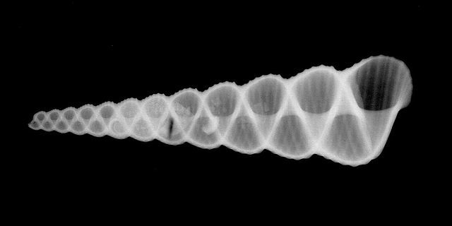 |
Radiograph of Snail Shell (Ua = 50kV, Ia = 1mA, Distance = 40cm, Exposure Time = 60s, Developer = Kodak D-72)
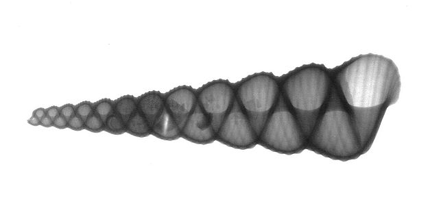 |
Inverted Radiograph
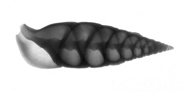
Here are two other snail shells (enlarged):
 |
Snail Shell
 |
Snail Shell
Later, I made some pictures of various electronic components. Image resolution is quite satisfactory. Even the very thin wires inside the IC and the transistor are visible.
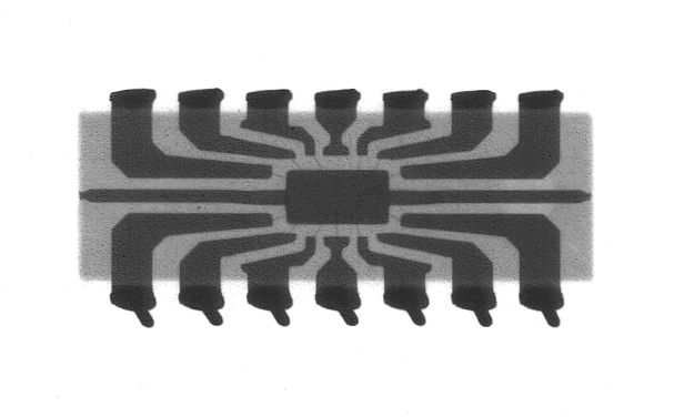 |
Integrated Circuit (SN7490)
 |
Small-Signal Transistor
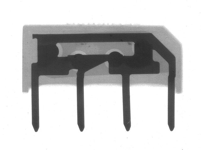 |
Rectifier Bridge
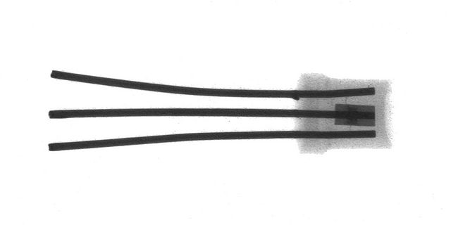
Here is a photo of a high-voltage rectifier from a microwave oven. The silicon crystal between the copper wires is hardly visible because of the relatively low extinction coefficient:
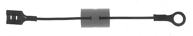 |
High Voltage Rectifier
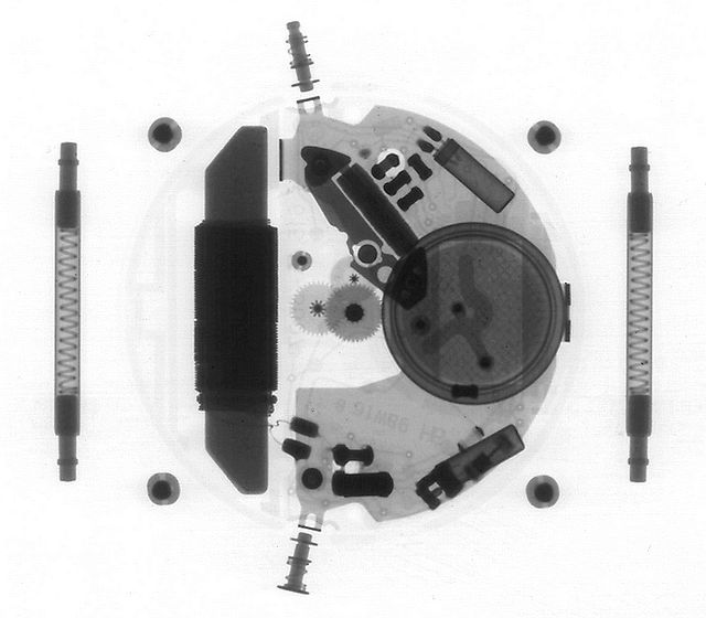
Below is a photo of a radio-controlled wristwatch. The plastic case and leather strap cast faint shadows because they are easily penetrated by X-rays. On the other hand, thicker metal parts like the antenna coil (left) and the battery (right) appear very dark. The hands are not visible, indicating that they are made of thin plastic. This time, the scanner resolution was set at 1200dpi to demonstrate the definition of the print.
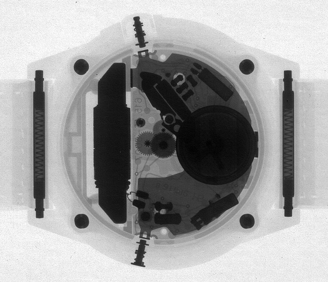 |
Radio-Controlled Wristwatch (U = 50 kV)
Here is a photo of the same watch made at 70kV. The metal parts are more transparent now, but the contrast is lower, and the plastic parts do not stand out well against the background.
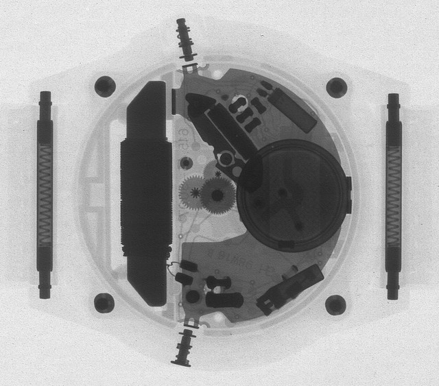 |
Radio-Controlled Wristwatch (U = 70 kV)
I found it very difficult to take pictures of flowers. Although I reduced the anode voltage to 40kV, the contrast of the print was so low that there was hardly anything to see. I had to use the graphic editor to optimize the picture. After increasing the contrast to a large extent, the result almost looks like a pencil drawing on coarse paper:
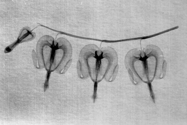 |
Bleeding Hearts
I had tried to take a picture of a cowry shell, but without much success because the material is rather opaque and requires a longer exposure time and higher voltage. Only after installing a heat sink, I was able to run the tube long enough to obtain an image of reasonable quality (120 mAs @ 70kV):
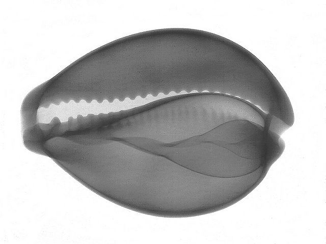 |
Cowry Shell
Here is a picture of a miniature electron tube (120 mAs @ 60kV). Details inside the anode cylinder (including the very thin grid wires) are clearly visible.
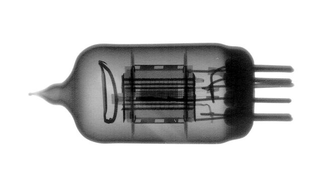 |
Electron Tube (6AK5)
The next picture is a 150 kV radiograph of a 6 mm steel drill (enlarged). Due to the extremely high voltage, I used a bigger tube this time (the one with the low output). The distance between tube and object was 55 cm (22"). The photo was underexposed, and I had to improve the picture with a graphic editor.
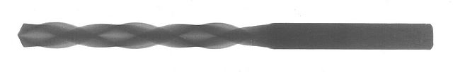 |
Radiograph of Steel Drill (90 mAs @ 150 kV)
Since ordinary photographic paper is much less sensitive than X-ray film, relatively high mAs values may be required, depending on the opacity of the object. Instead of increasing the mAs value (and reducing tube life), one can use a film holder containing an intensifying screen to increase the exposure of the paper. The screen is in close contact with the surface of the photographic material and emits green or blue fluorescent light when irradiated. The paper is exposed by this light and, to a smaller extent, by the X-rays penetrating the screen. Thus, the mAs value can be reduced considerably. Intensifying screens are used in medical X-ray diagnostics to keep the radiation dose as low as possible. The photo shows an opened film holder with two intensifying screens (in contrast to ordinary photographic film and paper, X-ray films have an emulsion layer on either side of the transparent plastic carrier to obtain a higher photographic density).
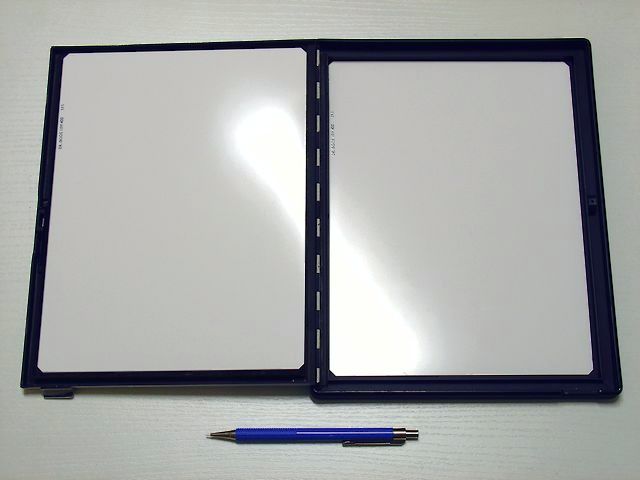 |
18×24 cm Film Holder with Two Intensifying Screens
The following pictures were made with such a film holder. Since I used photographic paper (one emulsion layer), I
covered the fluorescent screen at the bottom of the film holder with black cardboard to prevent the emulsion from
being exposed by diffuse light coming through the paper/plastic carrier.
The first radiograph shows the radio-controlled wristwatch described earlier (7 mAs @ 70kV):
 |
Wristwatch Photographed with Intensifying Screen (3M Trimax T2)
The dense parts have become even more transparent than before. The copper wire of the antenna coil stands out
against the ferrite core now. Even the wafer structure inside the battery is clearly visible. On the other hand,
almost all plastic parts are gone. One of the circuit boards remains visible because one side is copper-plated.
The image contrast is much higher than without the intensifying screen, so I used grade 3 paper instead of grade
4. Intensifying screens reduce image sharpness because they emit diffuse light. Particularly overexposed images
tend to show blurred edges. Still, the photo reveals enough details. To make the photo look a little better, I
used the sharpening tool of the graphic editor.
Here comes a chicken bone with some flesh on it (10 mAs @ 60kV):
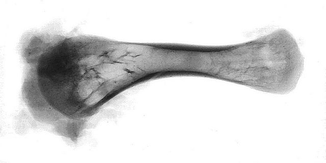 |
Chicken Bone
The picture reveals that the greatest part of the bone is hollow. Therefore, the bone was much more transparent than I had thought, and the chosen exposure time was too long. As a result, the paper was overexposed, and I had to increase the contrast electronically after scanning the image.
Will be continued...